NAO Ammonia Flares
-- Emergency & Process
Home Products FLARES
Rentals
Services
Tech
Section Users
Ammonia flares are of two (2) general types;
a.) emergency (refrigerated
ammonia storage terminals, steel mills, food processing) and
b.) process (chemical plant producing ammonia).
A.) Emergency
The emergency ammonia flare is a NFF-CG™ (NAO Fluidic
Flare - Clear Glow™) which includes
1.) high
performance vortex flame retainers (Vortuswirl Vanes™) to assure flame
stability and high
combustion efficiency, 2.) reliable pilots for light off of the
ammonia gas and 3.) emergency battery
backup ignitor, if required, as is the
case for low pressure refrigerated
ammonia storage terminals.
 Note:
Thermal radiation from an ammonia flare is minimal since
Note:
Thermal radiation from an ammonia flare is minimal since
ammonia only has
nitrogen and hydrogen. Combustion produces
nitrogen and water vapor.
Nitrogen is a very poor radiator of heat
and water vapor is a weak
radiator. Since ammonia has no carbon
present (which acts as a strong
radiator -- BLACK BODY), overall
heat radiation on the storage tank and
equipment is not of major
concern. The radiation levels should be
calculated and checked
for operator safety concerns only.
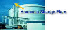
Low Pressure Refrigerated Ammonia
Storage
Typically, the flare is mounted on top of the access stair support column
along the side of the low pressure
refrigerated storage tank. Operation of
the flare only occurs in the event of refrigeration failure or power
failure. Since refrigeration failure is very unlikely, the prime cause of
a flare event is a long term power
failure. A short power failure will
cause the cooling compressors to shutdown but the thermal mass and
insulation of
the storage tank will maintain the ammonia pressure below the safety relief
valve settings.
However, a long term loss of power, especially during the
summer with high ambient temperatures and
intense solar radiation (sun beating
on the surface of the tank), will result in tank pressure build-up and
the
opening of the safety relief valve. The flare must be ready for the
ammonia gas relief with its pilots
ignited and proven. The flare operation
is a simple OFF-ON-OFF operation, i.e., tank pressure normal
-- relief valve
closed, pressure build up -- relief valve open, flare ammonia vapor -- reduce
tank pressure,
pressure back to normal -- relief valve closes.
Ammonia Emergency Relief -- Nitrating
in Steel Mill or Refrigeration in Food Processing Plant
Normally, these flares are NEVER used, except in the
emergency or equipment failure. Typically, the flare
is mounted on a short
elevated flare stack or on the roof of the plant. Since radiant heat from
the flare is
small, normally stack height is only 10' or 20' depending on the
size of the relief load. The pilot(s) and
ignitor are automatically
actuated by means of pressure or another remote signal. Backup battery
power
and a small LPG cylinder are normally provided for safety and reliability.
B.) Process
A process flare combines the operation of an emergency flare with small
intermittent flows due to process
variation and control. A process flare
must be able to handle high emergency flow rates and low flows
(typically 1/10
to 10 percent of the emergency). These low flows are difficult to burn
completely due to
their very low exit velocities, low momentum and crosswind
dilution/quenching.
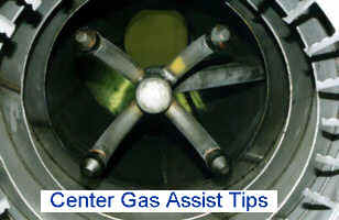
NAO has produced two (2) flare models to solve this problem;
1.) Gas assist flare with center and/or ring gas injection -- the flare
produces an intense ring (halo) of fire at
the flare tip to insure complete
combustion. The NCGA™ (NAO Center Gas Assist™) and NGR™ (NAO
Gas Ring™ Assist) Flares are
used when flaring is normally infrequent, thus minimizing assist gas
usage.


2.) For applications, with more continuous flare flows, a Regenerative flare with assist gas is used. The
regenerative flare
has a refractory lined tunnel to initiate combustion and restrict excess
air/crosswinds.
The amount of assist gas used is reduced with the NRG™ (NAO
Regen Flare™). For many gas streams
and mixtures, the regenerative flare only needs assist gas for initial warm up and then is self-sustaining.
Regenerative are available in both elevated and enclosed models. The
enclosed regen flare can include
even better air control thus further reducing
assist gas needed. The enclosed flare can also be equipped
with sample
ports and emissions monitoring to confirm overall performance.
For more information, please call, fax or Email for
typical drawings, technical
reports, price and brochures.